Aruco tags, in case you don’t already know, are a bit like QR codes: images with data encoded into the position of coloured squares. They’re part of OpenCV which can detect them, and their positions, in camera images. That’s very powerful and for things like 3D scanning allows us to work out where the camera is looking. Normally they’re either printed on paper or displayed on a monitor, which works very well. But I wondered how easy it would be to make more durable 3D printed versions, so I wrote some code in Python 3 to do just that, which I’ll tell you about in this post.
Obviously I could have used a library like PyCSG to create 3D models to print, but to allow customisation I decided to get Python to generate an OpenSCAD file instead. Simply put, the OpenSCAD code creates a thin cube and then uses constructive-solid-geometry (CSG) to cut holes out of it where the white squares would normally be. Making an OpenSCAD file to do that in Python is quite simple once we have the Aruco tag data. However, before I start with the code (all of which is on the Parth3D Github repo to make life easier) I should mention that not all tags will work: as shown for 4×4 Aruco tags below, some will produce islands of squares not attached to the tag (e.g. tags 9 and 12 are good examples).
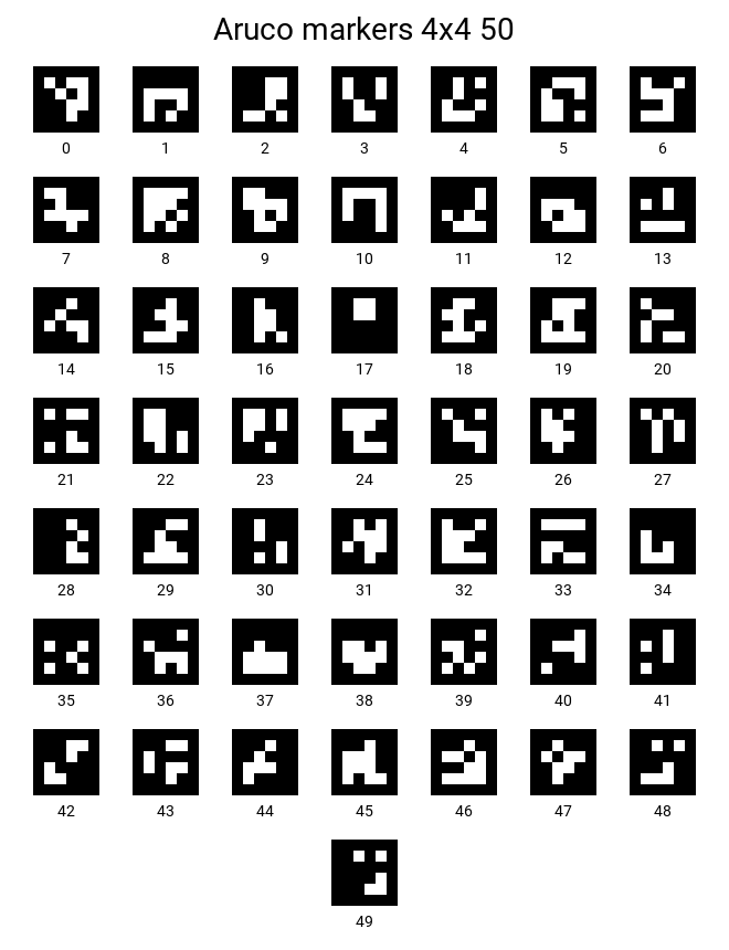
So please choose the tags you want to use with care for 3D printing. And having done that we need to start by importing some libraries. The main one is the cv2 library (from the python OpenCV library), which we will use to generate the positions of squares for individual tags. It uses numpy to provide those data in an array, so we import that too. Matplotlib we will use just to display a plot of the tag data.
import numpy as np
import cv2
from matplotlib import pyplot as plt
Now we need a way for OpenCV to create an array representing the squares in the Aruco tag. For that purpose we can use the function below to get data for tag ‘num’ in the ‘tsz x tsz’ dictionary. If you don’t know much about Aruco tags, dictionaries are just collections of tags of different sizes. So, a 4×4 dictionary has tags four squares wide and high, whereas for a 6×6 dictionary it would be six high and wide. For each dictionary there are variants known as 50, 100, 250 and 1000 representing the number of unique tags the dictionary contains.
def getTagArray(num, tsz):
    # DICT_MXM_N
    # M is number of blocks 4 ... 7
    # N is number os possible tags 50, 100, 250 or 1000
    if tsz == 4:
        dict = cv2.aruco.DICT_4X4_50
    elif tsz == 5:
        dict = cv2.aruco.DICT_5X5_50
    elif tsz == 6:
        dict = cv2.aruco.DICT_6X6_50
    elif tsz == 7:
        dict = cv2.aruco.DICT_7X7_50
    else:
        return False
    tags = cv2.aruco.Dictionary_get(dict)
    pixels = tsz + 2 * 1 # Tag plus border pixels
    tag = np.zeros((pixels, pixels, 1), dtype="uint8")
    cv2.aruco.drawMarker(tags, num, pixels, tag, 1) # 1 is border pixels
    return tag
Obviously the more tags the dictionary contains, for a set number of squares, the greater the potential for confusion when detecting them. Hence the code only uses the 50 variants, but you can easily change that. And it returns a numpy array of the squares, so all we need now is to be able to generate the OpenSCAD code. For that we can use the functions below. The ‘makeCubeScad’ function simply generates text for a single cube, which makes the ‘makeTagScad’ function much simpler than otherwise. Note the ‘adj’ parameter: it lets us make the squares a little larger to prevent CSG problems with adjacent squares that have zero overlap.
def makeCubeScad(dx, dy, dz, ox=0, oy=0, oz=0):
    txt = ""
    if ox != 0 or oy != 0 or oz != 0:
        txt += "translate(["
        txt += str(ox) + ", " + str(oy) + ", " + str(oz)
        txt += "]) "
    txt += "cube(["
    txt += str(dx) + ", " + str(dy) + ", " + str(dz)
    txt += "], center=true);"
    return txt

def makeTagScad(tagdat, psz, bmm, sqmm, dmm, adj=0.01, upsidedown=False):
    scad = ""
    tagsz = (psz * sqmm) + (2 * bmm)
    scad += "difference()\r\n{\r\n"
    line = "  "+makeCubeScad(tagsz, tagsz, dmm, 0, 0, dmm/2) + "\r\n"
    scad += line
    start = ((psz / 2) * sqmm) - (sqmm / 2)
    for y in range(0, psz):
        for x in range(0, psz):
            if tagdat[y+1][x+1] > 0:
                if upsidedown:
                    px = start - (x * sqmm)
                else:
                    px = -start + (x * sqmm)
                py = start - (y * sqmm)
                line = "  " + makeCubeScad(sqmm+adj, sqmm+adj, dmm*5, px, py, 0) + "\r\n"
                scad += line
    scad += "}\r\n"
    return scad
So let’s use the above code to make a tag. To do that we can define the parameters for our function calls, get the tag data array and generate the SCAD code as text, as shown below. I chose the values here to get a tag 60mm square, 0.7mm thick, with 10mm square holes and a 10mm ‘quiet zone’ border around the edges. But feel free to adjust the parameters: some combinations may be better than others for detection in images, but we only find out if we try. And I set the code to generate the tag upside-down, as the side of the 3D printed output against the print bed is generally flatter than the top (but you can set it to False if you prefer).
tagnum = 11 # Aruco marker number (starts at zero)
tagsize = 4 # Square horizontally and vertically

bordermm = 10 # Quiet area width around marker (mm)
squaremm = 10 # Width and height of each pixel square (mm)
depmm = 0.7 # Depth of tag (mm)

tag = getTagArray(tagnum, tagsize)

scadtxt = makeTagScad(tag, tagsize, bordermm, squaremm, depmm, upsidedown=True)
Now let’s save the SCAD text to a file, so we can open it in OpenSCAD. That’s easy to do in Python, just using the below code. To make life easier it even names the file properly so you know which file contains which tag and from which dictionary.
fname = "aruco_" + str(tagnum) + "_" + str(tagsize) + "x" + str(tagsize) + "_50.scad"
with open(fname, "w") as fp:
    fp.write(scadtxt)
If you open the file now you should see CSG code just like you write yourself in your own OpenSCAD projects. For the example above it should look like this:
difference()
{
translate([0, 0, 0.35]) cube([60, 60, 0.7], center=true);
translate([-15.0, 15.0, 0]) cube([10.01, 10.01, 3.5], center=true);
translate([-15.0, 5.0, 0]) cube([10.01, 10.01, 3.5], center=true);
translate([15.0, -5.0, 0]) cube([10.01, 10.01, 3.5], center=true);
translate([-5.0, -5.0, 0]) cube([10.01, 10.01, 3.5], center=true);
translate([5.0, -15.0, 0]) cube([10.01, 10.01, 3.5], center=true);
translate([-5.0, -15.0, 0]) cube([10.01, 10.01, 3.5], center=true);
translate([-15.0, -15.0, 0]) cube([10.01, 10.01, 3.5], center=true);
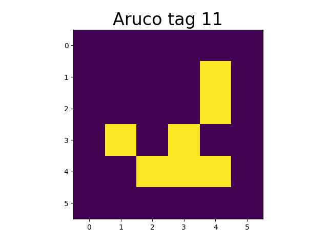
}And if you’re curious as to what the tag data array looks like, you can add the below code to plot it using matplotlib. Note that the matplotlib imshow call automatically converts the numpy array to an image, saving us having to do it ourselves.
plt.imshow(tag)
plt.title("Aruco tag " + str(tagnum), fontsize=24)
plt.show()
If all goes well you should then see a plot like the one below.
And that’s all there is to the coding. All that’s left is for you to run the generated CSG file in OpenSCAD and 3D print the STL file you save from there. Then you can take a photo of the tag against a light background (or stick some white paper/plastic to the back) and try to detect it in OpenCV. As my 3D printer tends to widen prints close to the flexible bed plate, I decided to try also making versions with plus and minus a millimetre around the holes. The results of detecting the three #11 tags are shown below.
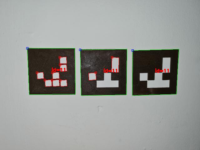
The red squares show where OpenCV is unhappy with the quality, due to the closing up of the squares on my 3D printer bed. So the image shows that using the ‘adj’ parameter in ‘makeTagScad’ to fine-tune the design can be useful for making the most-detectable tags. However, all three versions worked, and could work better with better lighting and after adjusting contrast. That’s useful, as the tag on the left does allow for using tags with squares that could cause plastic islands in 3D prints.
And that’s it for this blog post. I hope you find it useful for generating your own 3D printed Aruco tags, and for playing with them to get the best detection rates in OpenCV 🙂


